Original text
Contribute a better translation
c Laboratory work presents an alternative to the mbed platform of different but simultaneously executed actions (pseudo-imultan). The basic concepts of the repetitive interruptions and the launch of the actions on the mobile systems are studied. At the end of the lab, information about multitask classes and how to correlate multiple actions based on sensors and actuators will be available.
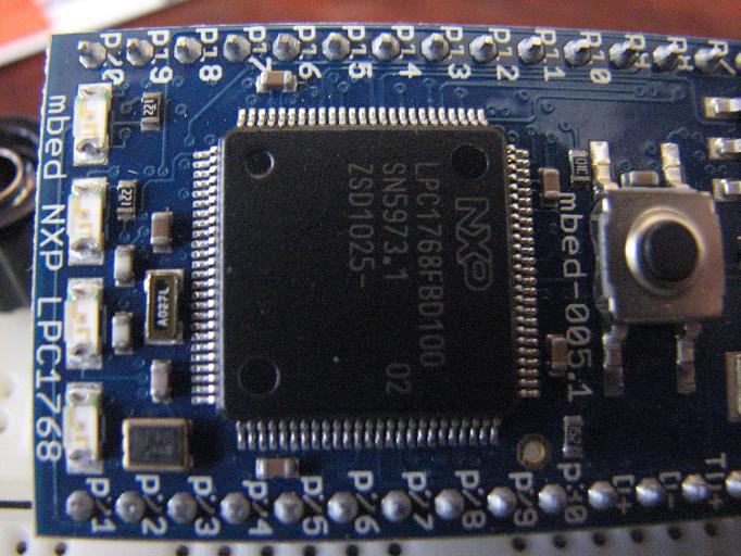
Platform MBED,

1. Perform a program sequence that will allow calibration of the servo position. 2. Make a program that will activate the 4 Random Frequency LEDs. 3. Perform a program sequence that will position the servo with maximum steering position and activate Led1 at the left edge of the steering wheel, ie Led4 when reaching the right-hand steering wheel. 4. Perform a program sequence that will allow the oscilloscope to view the servo positioning signals at 180 degrees and the Led1 blink at a 0.2 second frequency. 5 Make a program that will display the steering wheel angle / position and make Blink Led1 if the steering wheel is turned to the left or Blink Led 4 if the steering wheel is turned to the right. Blink operation will be performed at a frequency of 0.25 Hz. The central position does not activate LEDs.
- Creating mobile systems with controllable steering with servo; - Realizing applications based on analog sensors and digital actuators; - Car steering operations; - Implementing multitask operating systems;
|