Universitatea Tehnica Iasi - Fac. Automatica
si Calculatoare
Embedded Computer
|
Luni, 4 Feb., 119
Ora 9:34

|
 |
Lucarea de laborator nr. 2

|
Controlul I/O de tip SW/LED pentru dsPIC DSC
Actionare motoare asincrone de putere mare
|
L2.2 Prezentare generala, scop.
|
The laboratory work aims to provide a model for the management of microswitch digital inputs and the activation of digital outputs provided with LEDs and optocouplers. It is intended to compile written C-code and program drawing (step-by-step execution on development sites with dsPIC33FJ256xxx) as well as tracking the execution of the machine code. The concrete example refers to a method of controlling large asynchronous motors using separate galvanic interfaces. At the end of the laboratory, they will have interfacing skills for the microcontroller with galvanic segmented extensions for power applications and connectable to dsPIC DSC through the general purpose ports.
Scheme dsPIC DSC Board
DsPIC Starter Kit 1 development system, USB interconnect cable, AC motor control extension,
MPLAB C30.
Prototype program
|
L2.5 Running / tracking experiment:
|
- MPLAB C30 is punched on the PC using the dsPIC Digital Signal Controller CD;
- Connect the USB cable between the PC and the dsPIC DSC Starter kit board to transfer the code.
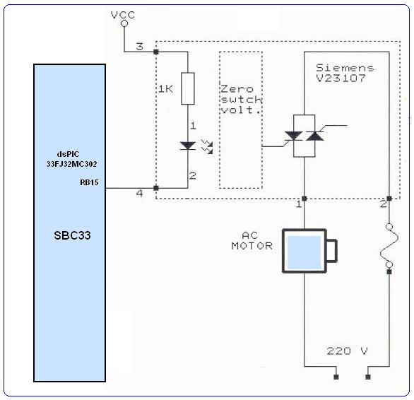
- The schema of optocoupler connection to dsPIC in the following figure is analyzed:
- A project with source L2motor.c is made in a personal directory;
- Configure MPLAB and the corresponding programmer accordingly;
- It is intended to get the HEX file and transfer it to the dsPIC DSC Starter Kit;
- Se analizeaza fisierele rezultate in urma procesului de compilare;
- Se urmareste executia corecta a programului;
- Se execta pas cu pas programul pe sistemul dsPIC DSC;
- Se rezolva problemele prototip;
- - Analizati structura interna a porturilor I/O
- - Examinati resursele biblioteca pentru controlul porturilor de I/O
- - Utilizind documentatia corespunzatoare, analizati
parametrii de curent continuu ale porturilor I/O
1. Realizati o secventa program care va permite activare LED verde cu intermitenta la apasare S2
2. Realizati un program care va semnaliza "avarie" daca se activeaza s1 mai mult de 500 ms;
3. Realizati un program care va activa motorul de curent
alternativ pentru 2 secunde daca se apasa simultan s1 si s2;
4. Realizti o secventa program care va activa motorul de CA
daca sint apsate s1 si s2
5. Realizti o secventa program care va activa LED-ul galben
simultan cu motorul de CA la apasarea lui s1.
|
L2.7 Experimentul poate fi extins pentru:
|
- Controlul sistemelor de putere actionate cu 220V;
- Realizarea secventelor pornire motor tractiune in vehiculele cu propulsie electrica;
- Realizarea intefetelor om-masina cu grad ridicat de siguranta;
|
L2.8 Referinte documentare:
|
.bmp) © 2019 Fl. Pantilimonescu - Fac. Automatica
si Calculatoare Iasi © 2019 Fl. Pantilimonescu - Fac. Automatica
si Calculatoare Iasi
|
|