Original text


Technical University of Iasi - Fac. Automatic and
Embedded Computer
Monday, 4 Feb.,
Time 11:53

Laboratory work no. 4

  • L4.1 Name:


  • Implementing multitask systems on dsPIC DSC


  • L4.1 Overview, purpose.


  • The lab work aims to explore a multitask application implementation using the timesharing concept. It aims at acquiring knowledge about the use of timers as well as the interrupt system for generating process time quantums. At the end of the laboratory there will be basic information about how to execute pseudosimultana of two different programs capable of controlling sensors (1) and actuators (2).


  • L4.3 Resources:


  • MPLAB C30 Documentation

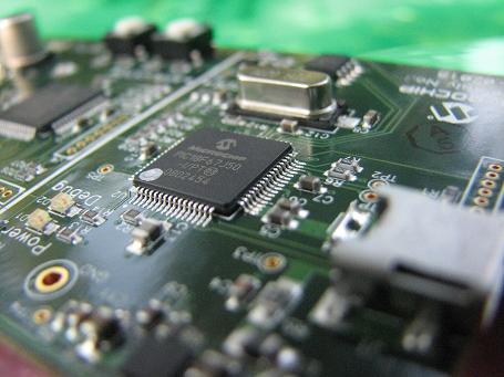
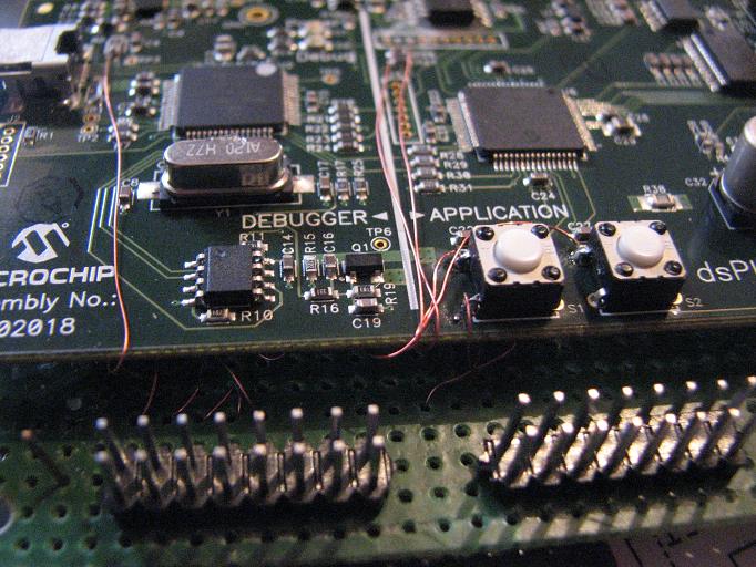
    Sistemul de dezvoltare dsPIC Starter Kit ,
    Extensie motor pas cu pas ,
    Cablu interconectare USB, osciloscop
    MPLAB C30.


  • L4.4 Sursa program prototip:


  • Program example
    Referinta documentare Timere


  • L4.5 Mod de desfasurare/urmarire experiment:


    • Se istaleaza MPLAB C30 pe PC utilizind CD aferent sistemului dsPIC Digital Signal Controller;
    • Se conecteaza cablul USB intre PC si dsPIC DSC Starter kit board necesar transferului codului.
    • Se conecteaza interfata pentru controlul motorului pas cu pas unipolar;
    • Se realizeaza un proiect cu sursa Timer1.c intr-un director personal;
    • Se configureaza corespunzator MPLAB si programatorul aferent;
    • Se urmareste obtinerea fisierului HEX si transferul acestuia pe sistemul dsPIC DSC Starter Kit;
    • Se analizeaza fisierele rezultate in urma procesului de compilare;
    • Se urmareste executia corecta a programului;
    • Se rezolva problemele prototip;

    1. - Analizati continutul registrelor INTCON1 si INTCON2 ( DS70053B- pag.6-17);
    2. - Analizati semnificatia informatiilor din registrele IFS0, IFS1, IFS2 (Interrupt Flag Status) ;
    3. - Analizati pozitiile binere specifice Timer-elor din registrul IEC0 ( Interrupt Enable Control Register 0)


  • L4.6 Probleme propuse:


  • 1. Make a program sequence that will allow you to calibrate the timing of supplying an interruption generated by Timer1.

    2. Make a program that will allow the generation of a 1.5 ms pulse and a 20 ms duration.

    3. Make a program sequence that will display the CPU priority level on the 3 LEDs;

    4. Perform a program sequence that will allow the operation of blink LEDs with the following frequencies: red LED 1/4 sec, yellow LED 1 sec, green LED 3 sec

    5. Make a program that will rotate the motor shaft by 1 step / second.

  • L4.7 The experiment may be extended to:


  • - Creating Kernel OS systems;
    - Implementing accurate metering of external events;
    - Implementing applications designed to generate digital controls with rigorous timing;
    - Achieving programmable signal generators;
    - Achievement of self-leveling frequency meters;
    - Realization of ultrasound generators;


  • L4 .8 Documentary references:


  • © 2012 Fl. ​​Pantilimonescu - Fac. Automation and Computers Iasi